Step 01/ 05
01
Brief & Scope
We start with how it will be made, not just how it looks. Loads, environments, tooling and budget define the design space — the drawing comes last, on purpose.
Pro Tool Design Solutions is a precision tool design and CAD engineering studio in Hosur, Tamil Nadu. We transform component concepts, samples, and drawings into production-ready press tools, dies, molds, jigs, fixtures, and 3D CAD assemblies — precision in design, excellence in tools.
We are tool designers, mechanical engineers, and CAD specialists in Hosur who transform component drawings and physical samples into precise, high-performance press tools, molds, and manufacturable tooling geometry — staying until every tolerance earns its place.

High-precision multi-stage progressive dies and compound press tools engineered for high-speed stamping, optimal scrap shedding, and extended die longevity.
Robust blanking, piercing, notching, and trimming dies engineered for high-volume automotive, electrical, and precision sheet-metal components.
Draw dies, wiping blocks, flanging stations, and re-strike tools designed with accurate springback prediction, corner relief, and tonnage balancing.
Comprehensive DFM review evaluating thinning limits, split risks, draw depths, and material yield to guarantee tool viability before manufacturing.
Station progression, carrier design, pitch calculation, strip width optimization, and pilot hole positioning for reliable, high-speed press feeding.
Rigorous geometric dimensioning and tolerancing per ASME Y14.5 and ISO standards, datum scheme formulation, and tolerance stack-up calculation.
Rigid CNC milling and turning fixtures designed with hydraulic/pneumatic clamping, poka-yoke locating, and zero tool-path interference.
Ergonomic manual and semi-automated assembly jigs, press-fit stations, and workholding tools ensuring swift, repeatable production-line operations.
Checking fixtures, flush-and-gap gauges, Go/No-Go plug and snap gauges, and CMM nest fixtures calibrated precisely to part datums.
Independent design audits of third-party tooling, 3D interference analysis, die clearance verification, and structural strength enhancements.
Complete lifecycle engineering partnership from initial part feasibility and 3D modeling through detailing, BOM generation, and tool room tryout troubleshooting.
Five stages, zero hand-waving. Every deliverable is versioned, checkable and ready for the shop floor.
We start with how it will be made, not just how it looks. Loads, environments, tooling and budget define the design space — the drawing comes last, on purpose.
Fast, rough 3D studies to compare architectures. You review real solids, not moodboards — and we kill the weak options early.
Fully parametric parts, mate-correct assemblies, drawings with GD&T. Every fillet earns its place; every feature survives a regen.
Tolerance stack-ups, FEA where it matters, motion and interference checks. We break it in CAD so you don't in production.
Native files, STEP and DWG packages, revision-controlled BOMs — plus a call with your manufacturer so nothing is lost in translation.
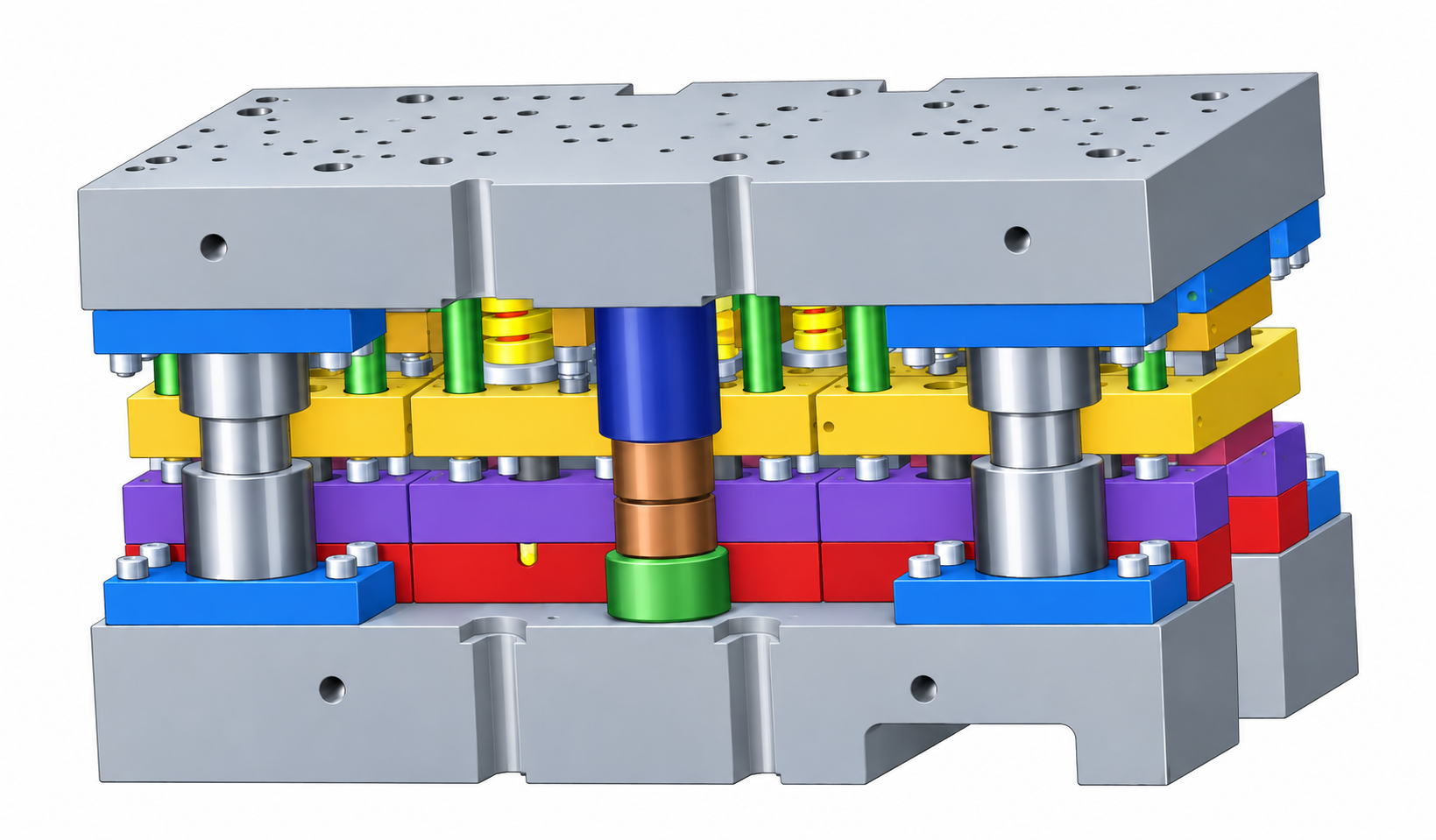 DIE.01 · PROGRESSIVE
High-speed progressive press tool featuring precision-guided punch and stripper assemblies, nitrogen gas return springs, and integrated strip carriers.
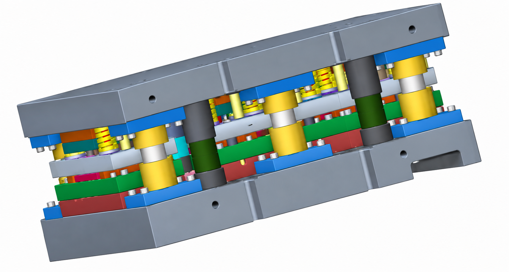 DIE.02 · PROGRESSIVE
Heavy-duty industrial stamping die with multi-pillar guidance, precision punch clusters, and scrap ejection channels for high-volume automotive parts.
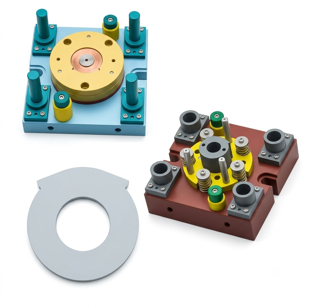 DIE.03 · COMPOUND
Simultaneous internal hole piercing and outer blanking in a single press stroke, achieving tight concentricity and flat, burr-free sheet blanks.
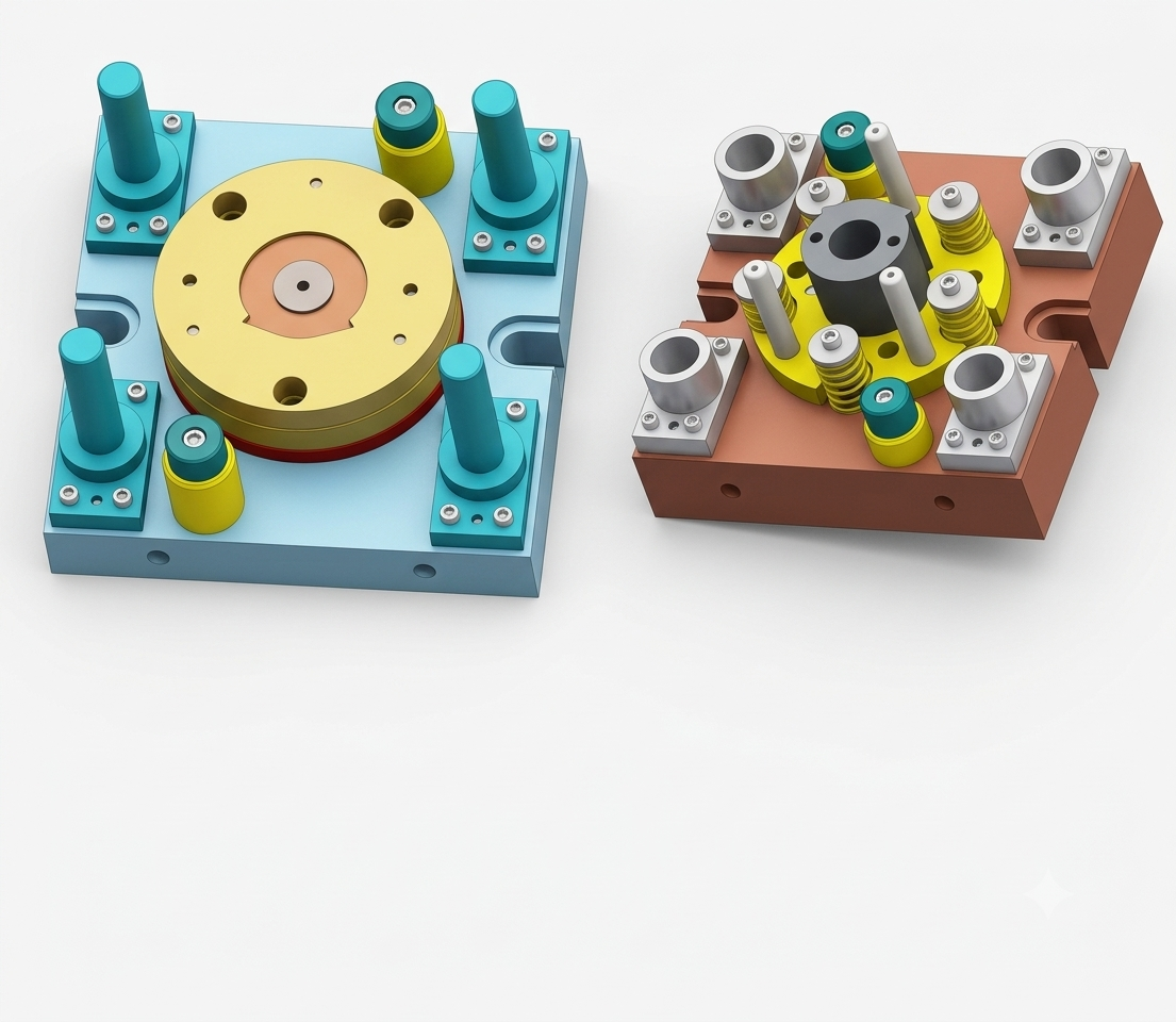 DIE.04 · TOOLING SET
Detailed CAD model of stripper plate retention pack, ball-bearing guide pillars, and hardened punch inserts designed for rapid maintenance changeout.
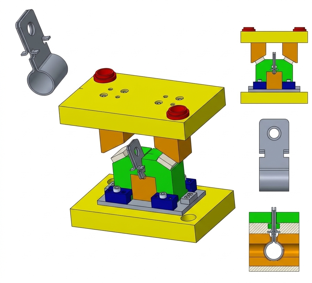 FORM.01 · CAM FORMING
Mechanical cam-slide tool engineered to curl and wrap sheet-metal strap brackets into tubular profiles with precise springback compensation.
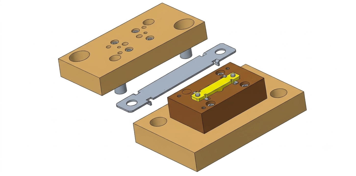 FORM.02 · STAGE TOOL
Two-pillar precision die set with central strip nest guide, hardened piercing punches, and cutoff blade engineered for precision link brackets.
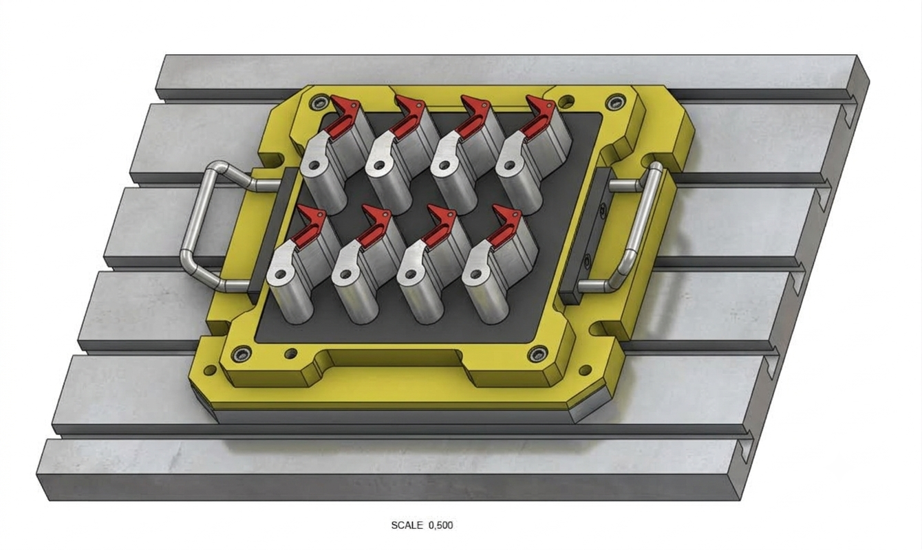 FIXT.01 · CNC JIG
8-cavity modular machining pallet with rapid toggle clamps, hardened locating pins, and hoist handles engineered for high-throughput VMC milling.
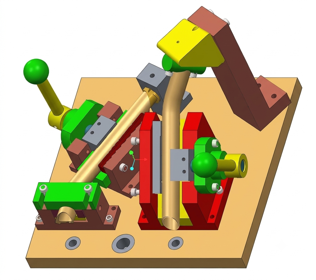 FIXT.02 · INSPECTION JIG
Complex pipe clamping, inspection, and welding fixture featuring toggle clamps, contoured bronze rests, and datum verification blocks.
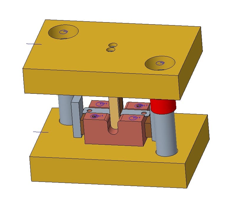 FORM.03 · FORMING DIE
Precision bottoming and channel-forming tool with robust guide pillars, hardened punch blade, and calibrated strip stops for consistent bend angles.
Mechanical Tool Design Engineer with 9.5+ years of experience in automotive tooling, specializing in sheet-metal stamping tools for automobile components and related manufacturing applications. Experienced from concept/feasibility through detailed design, manufacturing support and tryout.
Tell us what you're building — a component sketch, sample, or 3D step file is enough to start. We'll come back within one working day with tool feasibility, timeline and a fixed quote.